My speedo has now been successfully converted from cable-driven (AKA mechanical) to electronic. Here's a bit of an explanation of how I did it.
My understanding (correct me if I'm wrong) is that there are 3 different speedo setups that exist on different year models and trims of the SW20:
1) Early SW20s with mechanical speedo sender and no cruise control (like my car originally).
2) Early SW20s with mechanical speedo sender and cruise control (I think there's an extra thing on the side of the mechanical sender which generates an electronic signal that is only used by the cruise control system).
3) Later SW20s with fully electronic speedo sender and gauge.
My car is a 1990 JDM SW20 Turbo without cruise control. Originally (prior to the conversion) it had a mechanical speedo sender in the gearbox with a rotating cable from the gearbox to the back of the dash cluster, and the cable-driven speedo gauge generated electronic pulses from the rotating cable and sent the pulses from the dash back to the ECU via a single purple/white wire. Please note that the conversion may require different steps for early SW20s with a cable-driven speedo AND cruise control, but I don't know as I don't have cruise control on my car.
When converting from a mechanical speedo to an electronic speedo, the normal approach is to swap out the entire dash cluster and change/re-pin the plugs to suit. This is definitely the best approach if you haven't done too much work to your original dash cluster already. In my case I had already done a lot of work to my dash cluster so I decided to take a different approach.
What I chose to do instead was to remove the cable-driven speedo gauge from the existing dash cluster and then modify the cluster itself so the electronic speedo gauge could fit into it. I think I'm the first person to ever attempt this. I had to carefully trim away a number of small areas of the white plastic housing behind the dash cluster, because the circuit board on the back of the electronic speedo interfered with it. Also, the mounting holes for the electronic speedo are in different positions compared to the cable-driven speedo so I had to drill some new holes. I had to cut and re-route some of the 'tracks' on the green overlay on the back of the dash cluster because they overlapped the new mounting holes for the electronic speedo (you can use a razor to scratch away the green coating and expose the copper track underneath, then you can solder a wire to it). The electronic speedo has 4 mounting holes which also act as electrical connections.
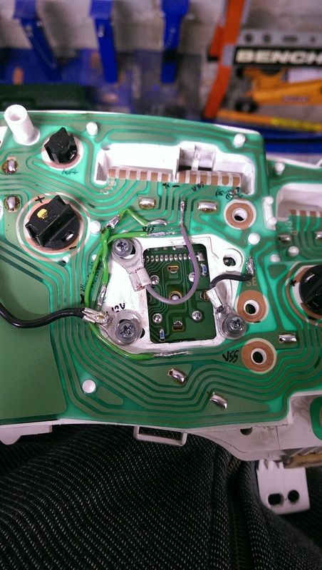
I did some research and bench testing to confirm that the 4 mounting holes on the electronic speedo gauge needed to be connected as follows (when looking at the speedo gauge from behind):
- Top Left = Speed signal from electronic sender in gearbox (I connected this to the track that goes to the purple/white wire back to the ECU)
- Bottom Left = Ignition-switched 12V
- Top Right = Unused
- Bottom Right = Earth
I used ring terminals on wires which I soldered to the relevant tracks on the back of the dash cluster, then I fastened the mounting screws through the ring terminals to form the electrical connections.
The sender in the gearbox was a straight swap from the mechanical type to the electronic type. I ran the 3 wires from the electronic speedo sender into the boot so I could easily connect them to the ECU wiring loom. For the signal wire from the electronic speedo sender, I simply tee'd it off the purple/white wire near the ECU (the same wire which already goes to the dash cluster). There's no need to run a new wire from the back of the car up to the dash cluster, because the purple/white wire is already there! The end result is that the electronic speedo sender in the gearbox now generates pulses on the purple/white wire, which is connected to both the ECU and the dash cluster.
I used the 'DigiHUD' Android app to confirm that the speedo gauge itself is showing the correct speed.
I can also confirm that the electronic speedo sender in the gearbox generates pulses at exactly the same rate as the original cable-driven speedo gauge in the dash cluster. I know this because my Adaptronic ECU still reads the correct speed without changing the calibration.
Here's a photo of the back of the dash cluster after the conversion. Please ignore the dodgily-sized ring terminals on the wires (they were the only ring terminals I had in my garage, and they already had wires attached to them, so I'll be redoing them later).
As you can see, the circuit board for the electronic speedo is visible through the rectangular hole where the mechanical speedo normally pokes out for the cable to attach to it.