• SHOWROOM
  • Stuka’s 1990 GT Turbo - Targa Tasmania Prep (p.11)
2017/01/22 10:20:48
5SGTE
Any pics of the header tank and associated plumbing? You've got me curious.
2017/01/22 10:54:01
Eric
Pat and I swapped cars for a few laps, i was extremely impressed with his car, especially the brakes! Bit of a handful though however ;)
2017/01/22 20:18:38
MCT_MR2
Good to hear the header tank worked. Means the issue your having is more a cavitation based issue then, and air pockets. If it hadnt quite done the job, id suggest bumping up the cooling system pressure if you needed it.
2017/01/24 20:35:12
stuka
5SGTE
Any pics of the header tank and associated plumbing? You've got me curious.

 
This is a very ghetto set up and I dont think anyone would learn from this, it aint pretty!!
 
MCT_MR2
Good to hear the header tank worked. Means the issue your having is more a cavitation based issue then, and air pockets. If it hadnt quite done the job, id suggest bumping up the cooling system pressure if you needed it.


Yes I believe this is the case. My suspicion is combustion gasses are gathering in the cooling circuit and starving the water pump. Its a very complex system (i.e. system dynamics), Im of the opinion there is a form of eddying in the region of the radiator side of the thermostat housing.
2017/01/24 20:58:50
5SGTE
Fair enough. Was more curious where you run the lines? I would assume from the return line/cold side?

I ask as my temp usually runs in the high 80s unless I'm giving it a hard time then it's low 80s and while I would like to a can't strap it everywhere :-S
2017/01/25 08:05:07
MCT_MR2
5SGTE, I'm not sure how Pat has plumbed his unit, but i can help shed some light if you like.


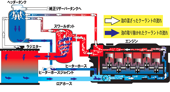
Here is the basic system diagram from when billion/arc used to sell universal swirl pot kits.


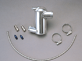
This is the swirl pot. it goes in the upper radiator hose. it is just a basic cylinder with offset radiator hose outlets opposite eachother, to get a swirl happening. This helps the air get bleed port, which is attached to the header tank.


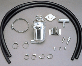
Then you have your header tank. This becomes both your pressure cap, and highest point in the system. You will have take off points to the swirl pot, lower radiator hose (engine bay one in an mr2), and you can also take off from heater hose points or other trouble areas if you wish.

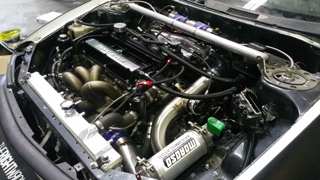
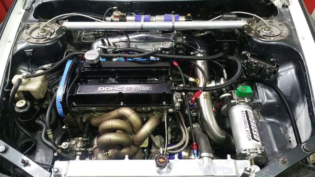
In my experience, i have found them highly effective if circuit vehicles. for an example, we have a shop evo, that we shift at 8800rpm. The standard evo water pump starts to cavitate at 8000rpm, and even with the system pressure bumped up to 1.5 bar, the system will still cavitate at around 8300rpm. the caviation would cause localised boiling, which would introduce air into the system. also pockets have normal areas that are hard to bleed. The header tank system allows the air to be better managed, and removed from the system during hard running.

Unfortunantley the ARC and billion kits are discontinued, but you could probably find an alternative, or have the bits required made up fairly cheaply. I have some rough pics of them installed on our shop car, where you can get an idea of an example of how the system can be setup:


2017/01/25 09:34:48
Falcon
Thanks MCT.  Fascinating stuff.  I sure would like to explore our cooling systems more.
If you have the time could you comment on why the thermostat is located in the suction side
(cold side) of the circuit and therefore requires the bypass circuit to trigger it's operation.
There must be a reason for setting it up this way but I can't figure it out.
Seems arse about face to me.
I have always believed the thermostat in the hot outlet from the head would be the most
restrictive spot to the flow therefore with the water pump hurling coolant into the lower block
would create significant pressure within the block and head as is typically required to press
the coolant into close contact with combustion chamber roofs especially.
I have heard of 20 30 40PSI. in some cooling systems when at full chat.
(within the block and head)
Interested in knowledgeable replies.
2017/01/25 11:28:31
5SGTE
Thanks for that MCT! There's even an unused port on the thermostat housing that seems like an ideal take off point for the cold side.
2017/01/25 23:26:04
MCT_MR2
Hi Falcon,

With advances in engine design and cfd etc, we moved from a simple thermostat, to our current bypass style thermostats. Now bypass style thermostats are used in the hot side and cold sides fairly equally.

Im not honestly aware of a benefit in using one method over another. I believe it comes down to packaging and engine design. Off the top of my head, any time a cold side thermostat it used (3sgte, rb20/25/26, 2jz, ej20/25) it can usually be packaged in close proximity to the water pump inlet.

Hot side thermostats are used in situations where packaging the thermostat near the water pump inlet isnt practical (4g63, 4age, b18c) interestingly enough, in the inline engines i have mentioned that use hotside thermostats, all three suffer issues with localised boiling the the head around the cylinder closest to the thermostat (cylinder 4)
2017/02/03 11:50:23
stuka
Thanks for the info Nathan and Doug, that all makes a lot of sense.
<< ..1112.. >> - Powered by APG vNext Trial
© 2025 APG vNext Trial Version 5.5

Use My Existing Forum Account

Use My Social Media Account